
KNX Switch Actuator Selection Guide
Choose a KNX switch actuator using real load data, not channel count alone. Compare relay ratings, LED inrush, feedback, manual override, and panel design.
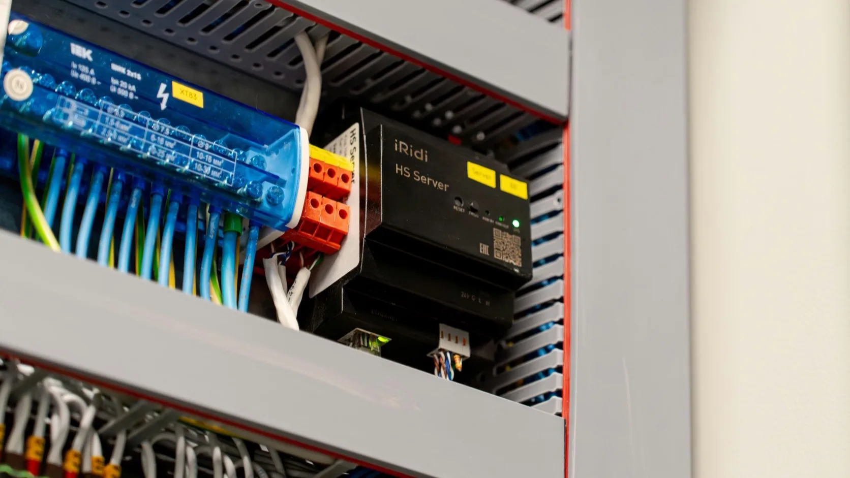
A KNX switch actuator looks simple on a schedule: eight channels, 16 A, DIN rail. That line is not enough to approve a device.
The relay must survive the actual load, the application program must expose the required behaviour, and the cabinet must remain serviceable. A 16 A resistive rating does not automatically mean the output can switch sixteen amps of LED drivers for years. Inrush current, capacitive loading, switching frequency, ambient temperature, and contact construction decide whether the selection is sound.
Start with a circuit schedule, not a catalogue
Before selecting the actuator, list every controlled circuit. For each one, record the protective device, steady current, load technology, number of drivers or power supplies, expected switching frequency, and required feedback.
| Circuit information | Example | Why it matters |
|---|---|---|
| Load type | 12 LED downlight drivers | Driver input capacitors create inrush |
| Connected power | 420 W total | Useful, but not sufficient on its own |
| Driver quantity | 12 | Many small drivers can be harder on contacts than one larger load |
| Protective device | C10 MCB | Coordination affects fault and cable design |
| Operation | Presence controlled, 30 cycles/day | Relay endurance depends on switching frequency |
| Feedback needed | Actual contact state | Determines actuator feature and group objects |
| Failure behaviour | Off after mains recovery | Must be parameterized and tested |
If the luminaire driver is not known, mark the channel “unverified.” Do not quietly replace missing data with the relay’s headline ampere rating.
Match the relay to the load
| Load | Selection risk | What to check in the actuator documentation |
|---|---|---|
| Resistive heater | High continuous current | Resistive rating, terminal limit, cabinet temperature |
| LED driver | High, short inrush current | LED load table, peak current/duration, maximum driver count |
| Fluorescent ballast | Capacitive starting behaviour | Ballast rating and permitted quantity |
| Contactor coil | Inductive switching transient | Inductive/AC-3 rating and suppression requirement |
| Fan or small motor | Starting current and contact wear | Motor rating; use an external contactor where required |
| Socket circuit | Unknown user load | Local regulations, contactor strategy, and operating policy |
Manufacturer load tables are more valuable than a generic “16 A” line. They may show different limits for incandescent lamps, capacitive loads, fluorescent ballasts, and LED drivers. If the product manual does not state the relevant load, ask for written confirmation or select a contactor interface.
Inrush current is the usual LED problem
An LED driver may draw only 0.2 A after startup but pull tens of amps for a fraction of a millisecond when its input capacitor charges. Twelve drivers switching together add their peaks. The cable and breaker may tolerate that pulse while a relay contact welds or erodes over repeated cycles.
Use the driver manufacturer’s inrush value and duration. Compare both with the actuator’s tested switching capacity. When only one side provides data, the calculation is incomplete. Splitting a large group across two relay channels can help, but only if the lighting design allows the groups to switch separately; paralleling relay outputs is normally prohibited unless the manufacturer explicitly permits it.
Features that matter after installation
Channel count and price dominate quotations, but service features determine how quickly a fault can be isolated.
Manual operation
Front buttons should allow the electrician to prove the load circuit before ETS commissioning. Check whether manual control works without bus voltage, whether it can be locked, and whether the manual state is reported to KNX.
Independent status feedback
A command object says what was requested. A status object says what the actuator believes happened. For reliable touch panels and toggle buttons, use the status object rather than echoing the command. Some products provide only software state; others include current measurement or contact monitoring. State clearly which one the project needs.
Mains and bus failure behaviour
Define the state after KNX bus loss, mains loss, mains recovery, application download, and device reset. “Restore previous state” may be suitable for some office circuits and wrong for a heater or exterior light.
Current measurement and diagnostics
Per-channel current data can reveal a failed lamp group, but it adds cost and group traffic. Specify measurement accuracy, threshold behaviour, reporting interval, and whether readings are for maintenance or billing. Do not describe a general monitoring function as a revenue meter.
Channel density versus serviceability
A high-density actuator saves DIN space, but it concentrates failure impact and can make terminal access difficult. Review:
- module width per channel;
- load terminal position and conductor size;
- heat dissipation when adjacent channels are fully loaded;
- ability to replace one device without disturbing many circuits;
- separation of essential, tenant, and common-area loads;
- spare channel policy.
For a project with 18 lighting circuits, a single 20-channel device may fit on paper. Two devices may be easier to phase, label, test, and replace. There is no universal answer; the cabinet drawing should make the trade-off visible.
Minimum specification table
| Requirement | Example wording |
|---|---|
| Certification | KNX certified product with current application program |
| Contacts | Potential-free, bistable relays where required |
| Load capacity | Proven for the scheduled LED driver/inrush data, not resistive rating only |
| Control | Switch, staircase timer, delay, lock/force, scenes as required |
| Feedback | Separate status object per channel |
| Local service | Manual operation and visible channel status |
| Recovery | Configurable behaviour after bus and mains voltage return |
| Documentation | English manual, load table, terminal data, application description |
| Security | KNX Data Secure where the project requires secured group communication |
Avoid copying every possible feature into the specification. Mark each function as required, optional, or not used. That prevents a long feature list from hiding the essential relay evidence.
Acceptance tests for a switch actuator
- Operate every channel locally before programming.
- Download the physical address and application through the intended interface.
- Test ON, OFF, status feedback, central command, and local override.
- Cycle the actual LED group repeatedly and watch for failed starts or welded contacts.
- Remove and restore bus voltage; confirm the designed state.
- Remove and restore mains voltage; confirm the designed state.
- Verify channel labels against the cabinet schedule and ETS group addresses.
- Save the final parameter set and application version in the handover file.
The acceptance record should name the circuit and output. “All lights tested” is not enough when a future technician needs to find channel 7.
FAQ
Is a 16 A actuator suitable for any 16 A circuit?
No. The stated rating may apply to a resistive load. LED, motor, ballast, and capacitive loads can have much lower permitted limits.
Should every lighting circuit have status feedback?
For touch panels, central visualization, toggle control, and integration, separate status feedback is strongly recommended. Decide whether software state or measured load state is required.
When should an external contactor be used?
Use one when the load type, current, inrush, isolation, local regulation, or switching duty exceeds the actuator relay’s documented capability. The KNX output then controls the contactor coil.
Are spare actuator channels useful?
Yes, if they are documented, wired appropriately, and do not create excessive concentration. Spare DIN space and power capacity are also necessary; an empty channel alone does not guarantee future expansion.
Technical references
- KNX Association product documentation, 10 A and 16 A switch actuators
- KNXmart, How to choose a KNX actuator
- KNXmart, KNX actuator load types and selection risks
A good switch actuator selection can be explained circuit by circuit. It connects the load data, relay evidence, cabinet layout, ETS behaviour, and acceptance test—without relying on the largest number printed on the datasheet.