
How to Choose a KNX Power Supply
Choose a KNX power supply by calculating bus current, checking the integrated choke, reserve margin, diagnostics, auxiliary output, and line topology.
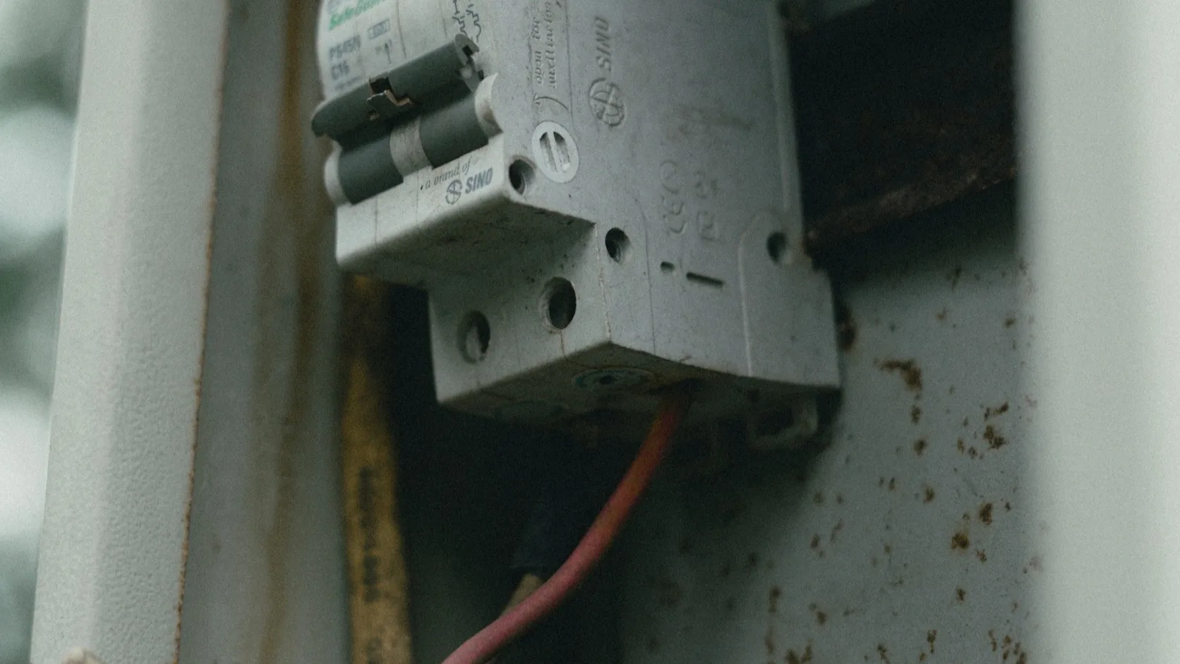
A KNX power supply is not selected by counting devices alone. The correct size comes from the actual bus-current data, line topology, operating margin, and recovery requirements.
For a small line, 320 mA may be enough. For a busy commercial line, 640 mA is common. Choosing the largest unit by habit is not a substitute for a current schedule, and choosing the smallest unit to save one module of cabinet space is poor value engineering.
What the KNX bus power supply does
A standard KNX TP power supply provides the SELV bus voltage and decouples telegram communication from the DC source through a choke. Many DIN-rail supplies integrate that choke. Some also provide an unchoked auxiliary output for equipment that needs separate DC power.
These outputs are not interchangeable:
| Output | Intended use | Common mistake |
|---|---|---|
| Choked KNX bus output | Powers a KNX TP line while allowing telegram communication | Treating it as a general 30 V DC output |
| Unchoked auxiliary output | Powers compatible auxiliary loads or another line through a separate choke | Connecting it directly as a second KNX bus line |
| Status/diagnostic interface | Reports current, voltage, overload, or device state | Assuming every supply exposes values to ETS |
Read the terminal diagram. Two outputs on the front do not necessarily mean two independent KNX lines.
Build a current budget
Use the current consumption stated in each device datasheet. Where the exact product is not yet selected, a provisional allowance may be used, but it must be replaced before procurement.
Required bus current = sum of all device bus currents + planned expansion + design reserve
An example line schedule:
| Device group | Quantity | Bus current each | Subtotal |
|---|---|---|---|
| Push buttons | 18 | 10 mA | 180 mA |
| Presence sensors | 8 | 12 mA | 96 mA |
| DIN-rail actuators | 6 | 10 mA | 60 mA |
| IP interface | 1 | 20 mA | 20 mA |
| Room controller | 2 | 15 mA | 30 mA |
| Installed load | 386 mA |
With expansion and operating margin, a 640 mA supply is the sensible class for this example. The values are illustrative; actual products vary.
A common engineering target is to avoid designing normal operation at the nameplate limit. A 20–30% margin is useful for drawing changes, replacement products, and measurement uncertainty, but it is an engineering allowance rather than a universal KNX rule. State the chosen margin in the calculation.
Current is only one limit
The number of devices permitted on a line depends on the KNX topology, the device/system profile, and the products used. Newer TP-256 equipment can change what is possible compared with older assumptions. Do not use “64 devices per line” as a universal sizing shortcut without checking the designed segment and couplers.
Also verify:
- maximum cable length for the line;
- maximum distance between the supply and a bus device;
- maximum distance between devices;
- line and area coupler arrangement;
- number and placement of power supplies permitted by their manuals;
- voltage drop at the furthest and most heavily loaded branches.
The supply can have spare current while the topology remains invalid.
160 mA, 320 mA, 640 mA, or larger?
| Supply class | Typical fit | Watch for |
|---|---|---|
| 160 mA | Small training board or compact dedicated segment | Little room for additions |
| 320 mA | Apartment, small floor, or moderate dedicated line | Touch panels and interfaces can raise current quickly |
| 640 mA | Commercial lines and projects needing practical reserve | Cabinet heat, total auxiliary load, and fault impact |
| 1,280 mA / special designs | High-current lines where topology and products support it | Product-specific rules; not a way to ignore segmentation |
Segmentation can be better than one large supply. Two lines provide fault separation and manageable telegram traffic, but require couplers, cabinet space, and correct filter-table planning.
Features worth specifying
Current and voltage indication
Basic LEDs may show normal, overload, and reset states. More advanced supplies display bus voltage, current, temperature, or historical load. Diagnostics are valuable in a remote cabinet because an intermittent overload is otherwise difficult to prove.
Reset control
A local line-reset button is useful, but it should not be easy to operate accidentally. If remote reset is provided, restrict and document it.
Short-circuit and overload protection
Confirm automatic recovery behaviour and what happens to auxiliary outputs during a fault. A short on one shared supply may remove both bus and auxiliary power.
Mains interruption ride-through
Product manuals may specify a short hold-up time. For buildings with generator or UPS requirements, coordinate the supply input with the electrical resilience design instead of relying only on internal ride-through.
Auxiliary output
Add every auxiliary load to the total rating when the outputs share a current limit. A 640 mA label may refer to the combined bus and auxiliary current, not 640 mA on each.
Should KNX power supplies be redundant?
Redundancy must be designed with products intended for that arrangement. Do not parallel two ordinary choked supplies on one line because it looks redundant. Manufacturer instructions govern separation, redundancy modules, and permitted topology.
Often the better first step is architectural resilience: separate critical and non-critical areas, avoid placing an entire building on one line, provide upstream backup power where required, and keep a tested spare supply with documented replacement steps.
Commissioning and acceptance checks
- Compare the installed device list with the current calculation.
- Measure bus voltage at the supply and at representative remote points.
- Record normal current with the complete line operating.
- Confirm overload, short-circuit, and reset indications using an approved test method.
- Check that auxiliary loads are included in the rating.
- Label the line, mains circuit, supply rating, and served area.
- Save the calculation and measured values in the handover pack.
The measured baseline matters. If a line draws 390 mA at handover and 570 mA a year later, the maintenance team has a useful lead even before opening ETS.
FAQ
Is 640 mA always the best KNX power supply size?
No. It is a common size, but the correct choice follows the current budget, topology, reserve, cabinet conditions, and fault-separation plan.
Can the auxiliary output power another KNX line?
Only through the required separate choke and when the product manual permits it. An unchoked output is not a direct bus output.
Can two KNX power supplies be installed on one line?
Some products and topologies permit multiple or redundant supplies under stated conditions. Follow the exact manufacturer rules; never assume ordinary units can simply be paralleled.
What voltage should be recorded?
Use the product’s specified KNX output range and project test procedure. Record measurements at the supply and remote points under normal load rather than relying on one cabinet reading.
Technical references
- KNX product documentation, 640 mA power supply with integrated choke
- KNX product documentation, 640 mA power supply and monitored SELV output
- KNXmart, planning KNX lines, areas, and power supplies
- KNXmart, diagnosing KNX bus voltage problems
The best selection leaves a calculation another engineer can audit: devices, current, topology, margin, auxiliary loads, measured baseline, and the reason that supply size was chosen.